Amstrad E2 and E3 emailers can now be picked up ridiculously cheaply. The goal of this page is to start to collate some useful information on "hacking" these boxes to do something useful. The hardware in these boxes is heavily subsidised so they are a potential bargain for hardware and software hackers.
For now I have just a couple of entries.
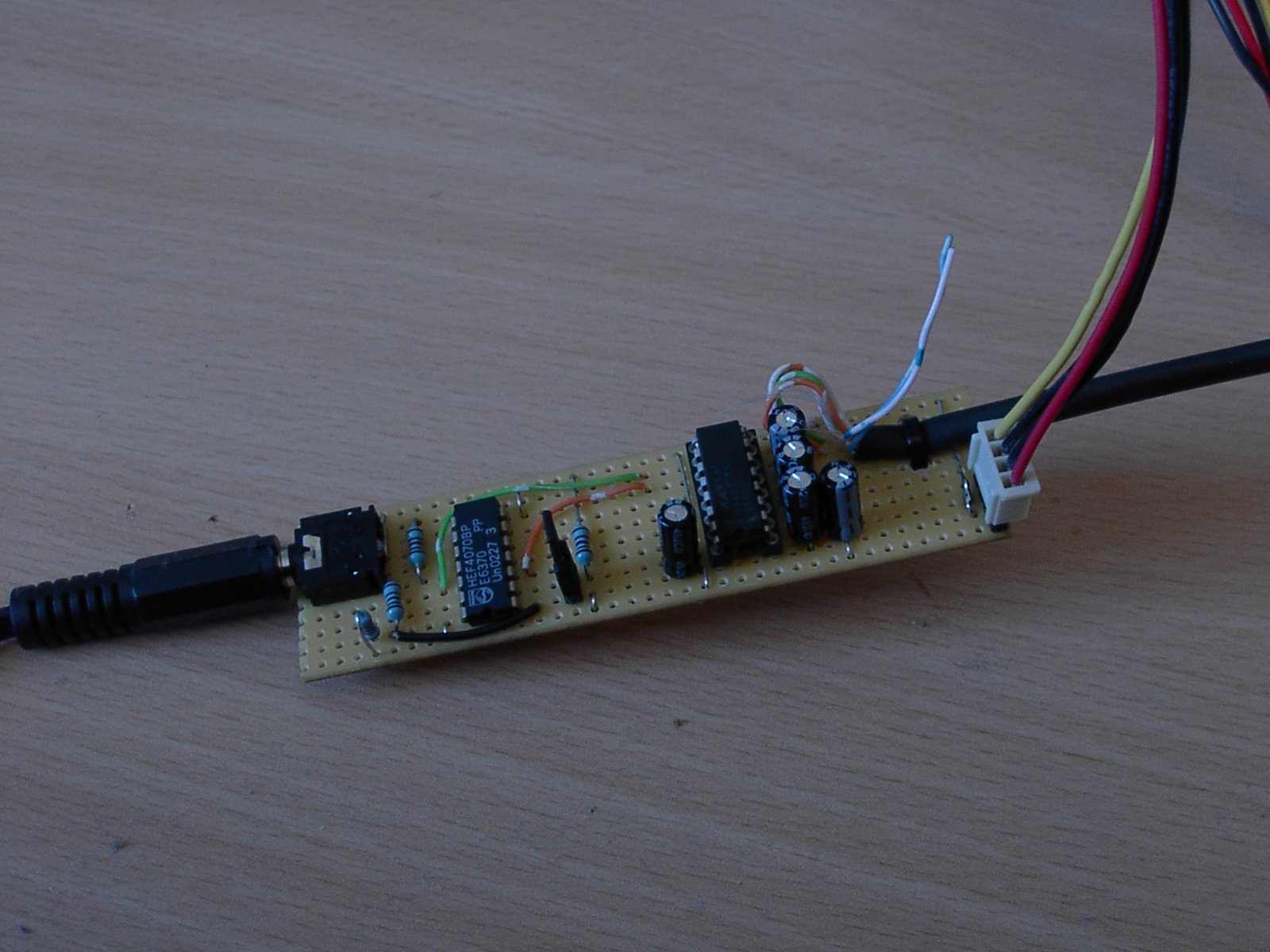
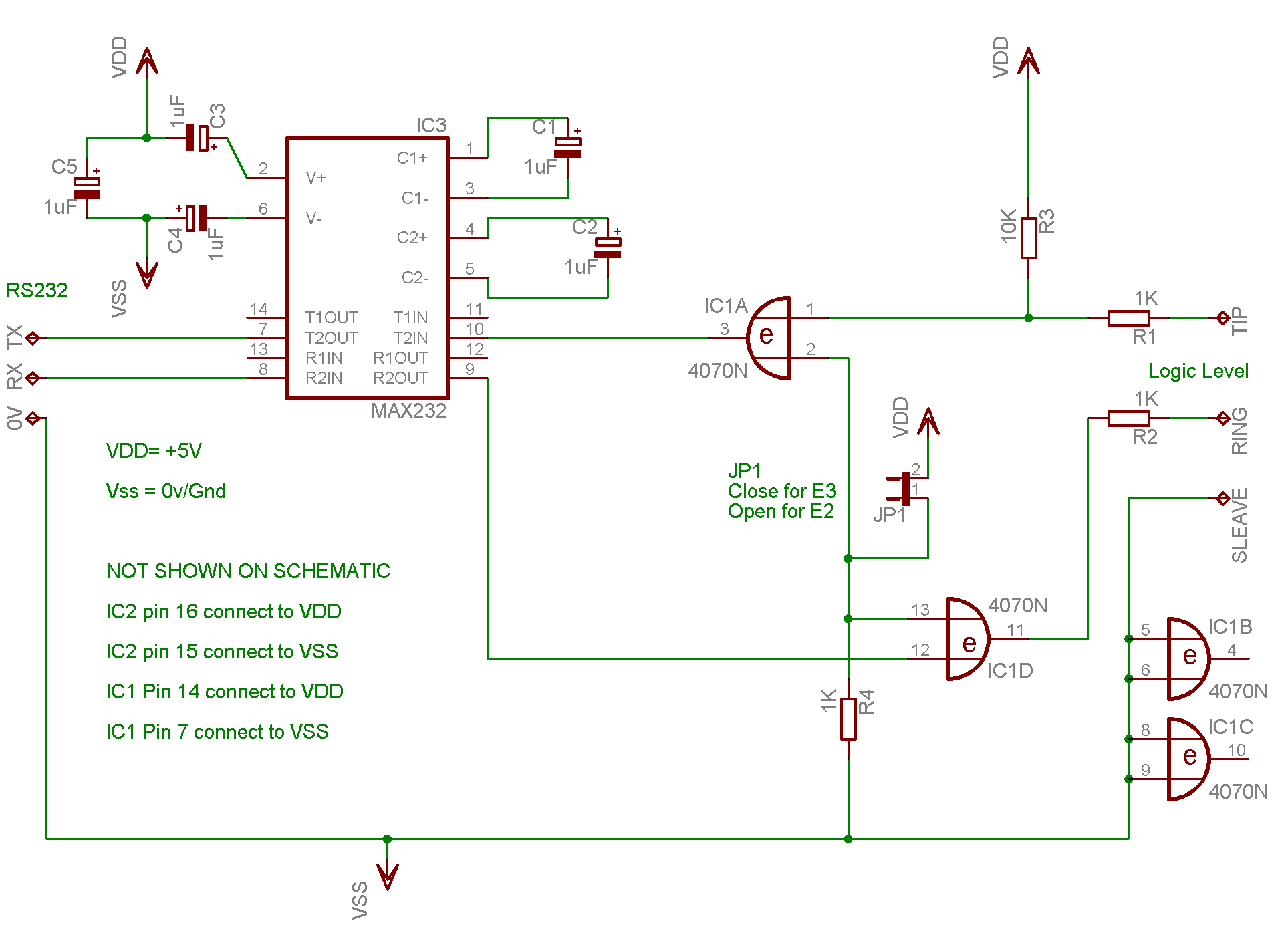
I've completed building and done some limited testing on a universal interface board that converts the output from either an E2 or an E3 to legal RS232 levels. A jumper can be fitted to select E3 mode. Otherwise it works in E2 mode. I've not connected this to an E2 yet.
I'll try to document this further in time, for now:
I used a package called "eagle" to produce the circuit diagram, from the prototype. This is the first time I've used this and I couldn't see a way to make it explicitly show the implicit power connections to ICs. There are some text notes on these in the diagram. IC3 should be labled IC2
I've deliberatly restricted myself to bits stocked by my local branch of Maplin. Thats why I'm using a 4000 series XOR gate and not something like a 74HC part... I'm not a fan of 4000 series ;-)
Feedback and sugestions welcome.
A tool called pbltool exists to talk to the PBL bootloader on the E2 and E3. Once you've got serial communication working. I can't recall where I found the source but I've put my local copy on this site.
A fair bit of confusion exists on the serial port of the E3 with some sources saying a line driver chip is needed, and other saying one is not needed, to connect this to a PC.
I've spent a bit of time looking at this and can now offer some explanation. A normal RS232 port will transmit a digital 1 as a negative voltage, usually at least -5V. A 0 is transmitted as a positive voltage, typically at least +5V. The emailer does not do this. Using a rather old poorly calibrated scope it appears to actually transmits either 0V or +5V.
Now some serial ports will probably accept this, but a 0V input is not a logical anything as far as the RS232 spec is concerned. So your PC, like mine, may ignore this. The fact that this works for some peoples PCs implies it is transmitting a logical 1 as 0v and a logical 0 as +5V.
A typical RS232 line driver expects a logical 0 to be 0v and a logical 1 to be +5v (or +3.3V if using a 3.3v device). So you end up with an inverted RS232 data and like me and see horrible gibberish on hyperterminal
Now, to get a boot log you need to invert the TX signal from the E3 (I used a 74HC04) then pass this to a line driver chip. The only line driver chip I had to hand was a MAX3233E, which is a 3.3 volt part. For this reason I ran both chips from 3.3V and placed a 100ohm resistor between the E3's TX pin nad the input to the inverter. Some logic families get very upset if you exceed the supply voltage on an input by more than about 0.6v... The series resistor limits the current and is a paranoia measure, quicker than looking up the datasheet :-) Anyway, it was a horrible quick bodge but it worked.
Here is the output captured from hyperterminal boot.txt settings were 115,200 8n1 no handshaking.
I'll try and post up a diagram of something better in the next few days. I've also built something for the reverse direction but havent had a chance to work out if its working yet....